

Nash “METROPOLITAN” Build ***
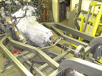
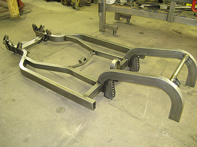
Shown below is an example of how we designed and constructed a Nash Metropolitan chassis sporting a new GM V6/305hp modular motor. We designed and mandrel bent the frame out of 2x4x11ga steel tubing using our “No wrinkle” technology. There are many challenges in building one of these chassis, dealing with the low fender openings in the front, the wide modular motor, and with the very narrow track width. Maybe ideas can be gained to help you with your next complicated project. *ON THE FIXTURE TABLE* *** The chassis was built in our prototype chassis table area. As you will see…Auto Weld quality is throughout. At this point the frame is almost completely designed and underway. It sports an Old style 9″ Ford rear, tubular a-arms, Aldan coilovers, our “Low Profile” 4-link, dropped spindles, and will have a power rack and pinion steering.
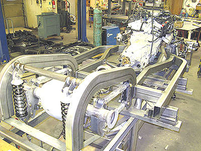
Note: To start a project like this, we first set and locate the motor and trans on the chassis jig. We then locate the spindles at the right location and position, after that …we are then ready to design the rest the frame and suspension.
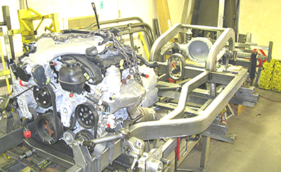
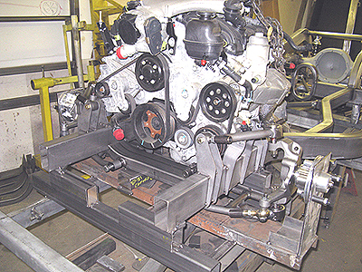
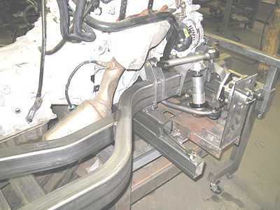
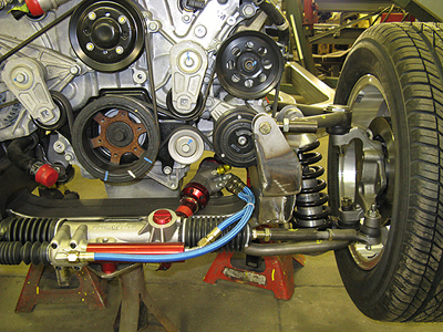
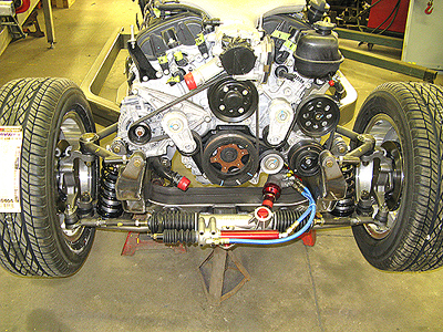
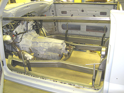
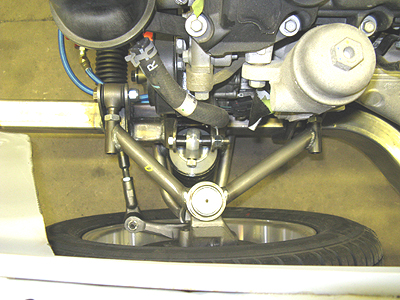
Shown below: note how the upper control arms wrap round the motor to get the needed front suspension geometry. *** NOTE: Modular motors are wide at the oil pan area as opposed to a conventional V6 or V8 which would provide more a-arm room.
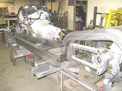
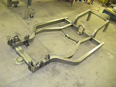
Because this is a convertible, the chassis has to be very rigid. Shown are the crossmembers and reinforcements.
Below: This picture shows just how involved the front suspension was to build. The custom bracketry for the coilovers and the special a-arms are just tacked into place for now. Finish welding will come later.
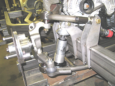
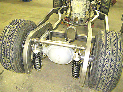
Our “Low Profile” 4-link was the perfect candidate for this project along with our shorter “Anglia” length links. It has lots of adjustment holes for instant center changes.
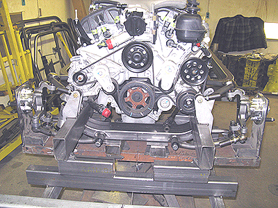
Close-up of the front suspension. *** The a-arms are fully adjustable and polyurethane bushed. “Aldan” coilovers, Mustang II dropped spindles and Wilwood hubs are also shown.
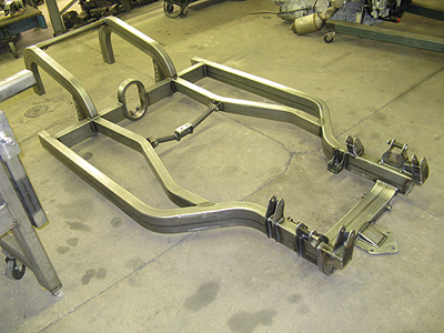
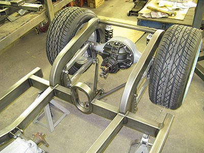
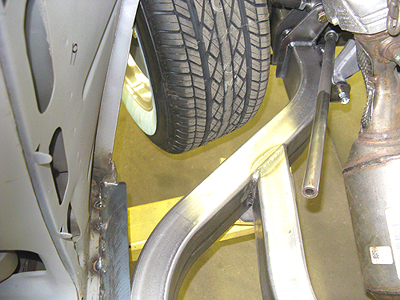
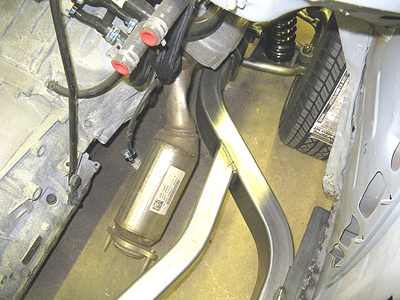
Below: Note how the frame rails wrap around the front of the chassis. Things to keep in mind are: tire turn, catalytic converter clearance, a-arm and coilover position.
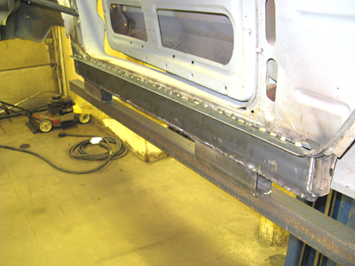
OFF THE FIXTURE TABLE *** Completed…well almost! Notice that the outer frame rails are designed to run along the rocker panel.
Looks simple now but was very complicated to design. Note the a-arm, coilover, motor and trans mounts, and the triangulated rack and pinion mount attached to the front crossmember.
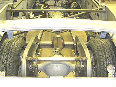
Shown from the rear are the smooth mandrel bent rails, oval driveshaft loop, 4-link, and coilover mounts…very sturdy.
A well designed chassis makes for a high-dollar car when completed. “AUTO WELD” quality is seen throughout. True art!
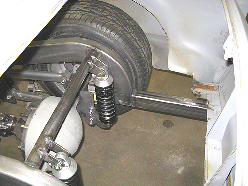
Below: Starting to take shape! Note the “wishbone” track locator. *** Why a wishbone? It doesn’t deflect like a “Panhard bar”. Especially good on a short narrow car.
From the back: The tires are not real big, but will look big under the body.
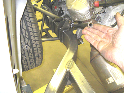
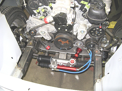
Note: Now dressed out…this is an example of just how crowded it can get. “Woodward Co.” is the only company we could find that makes “power” rack & pinions with a ball width narrow enough for this build. We got it to work out while maintaining zero bumpsteer to boot! *** WOODWARD racks have an external power slave and the servo is on the steering shaft. The servo can be rotated for clearance. These are ideal for complicated builds.
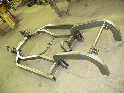
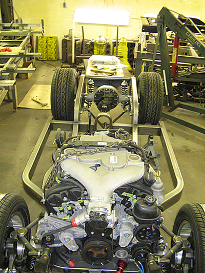
Full view: Good geometry is built in…positive caster, anti-dive, zero bumpsteer…. all the good AUTO WELD stuff.
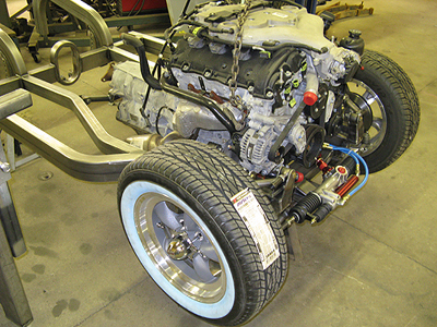
Position of the motor and trans will help with the balance of this short car.
Below: a very nice platform for our Metropolitan project. A true hot rod!
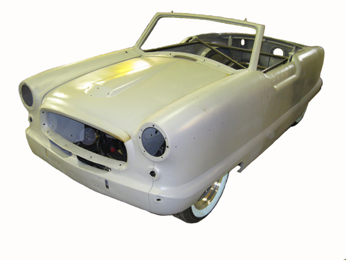
BODY FIT This is how we install the body shell onto the new frame. The floor-pan has been dropped out, trimmed and cleaned. Fortunately this body is very solid. No structural rebuilding was required. Note: The inner rocker panel has been removed. 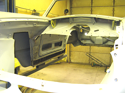
To keep the body from moving out of shape, we always weld supports across the inside of the body shell in several key areas as shown. This is done BEFORE the floor-pan is removed. Also notice the supports attached to the bottoms of the rocker boxes that are then held to the lift. 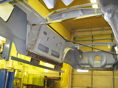
Since the new frame will run along the rocker panels, a support with an added lip was welded into position. This not only adds strength, but the lip makes it very easy to align the body. *** Below: C-Clamps are used to hold body into position.
Body is now located and centered. Note: The 1×1 reinforcements will stay in until the the body is permanently mounted.
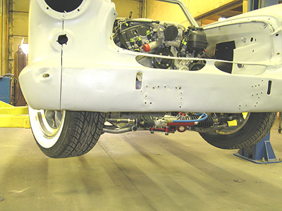
One thing to keep in mind when building a chassis like this is the clearance for when the tires turn.
The steering shaft clearance is tight, but adequate. *** Note: a strut rod stands in place of the coilover shocks at this time.
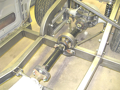
We used the OEM driveshaft, but both halves had to be shortened. Note: The carrier bearing was mounted to the oval crossmember. The hole unit looks factory and worked out perfectly.
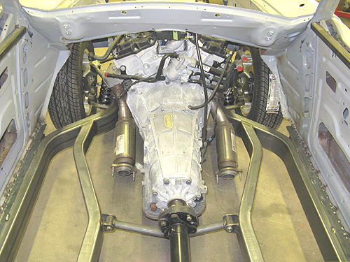
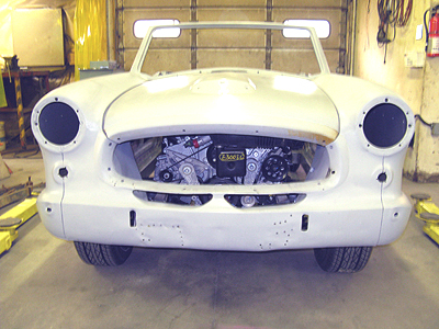
BELOW: Even though the motor has a setback, and the firewall will have to be custom made, it will still provide adequate leg room.
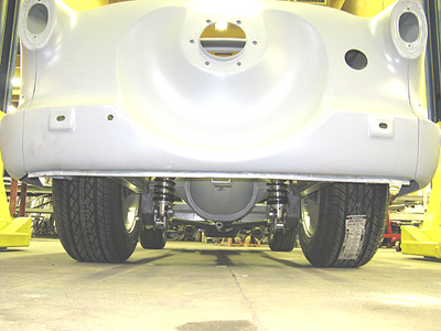
Note how this well designed frame wraps around the catalytic converters and also allows for the tires to turn. Also note the “smooth” bends of the frame rails.
This is as close as it gets. Sometimes you have to engineer something that can’t be done. Fortunately nothing had to be stripped off the motor. Shown below are the coilovers, and a-arm locations and how they wrap around the motor accessories. This had to be done to get enough a-arm length for the suspension to work properly. *** First picture…Passenger side Second picture…Driver side 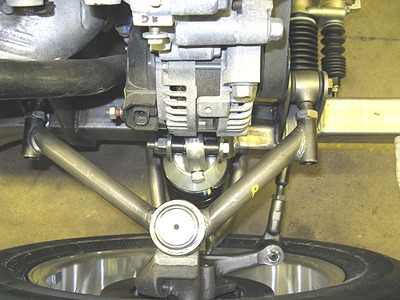
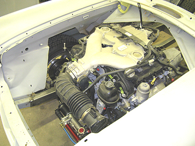
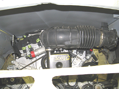
Below: Engine bay closure will be fairly simple. Looks like the GM V6 belongs there.
BELOW TWO PICTURES: 2×3 tubing was extended from the new chassis forward to the body frame stubs to complete the unibody structure. The same was done in the back car to attach the rear of the body to the new chassis. The frame was then finish welded.
BELOW: Hood clearance is fine. A good rule of thumb would be ….if you can slide your hand between the top of the motor and the hood….your safe. Fortunately this motor was the right height for this build.
BELOW: Even though the body is not very tall…we were still able to have good ground clearance and have a low center of gravity. *** NOTE: never run an oil pan less than 4″ off the ground, at “ride height”, on a street car!!!
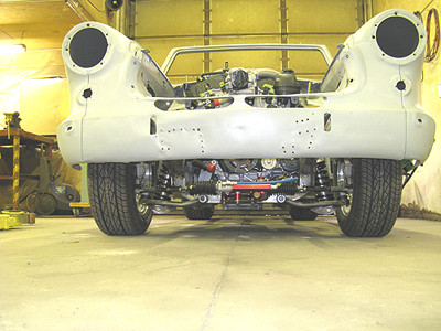
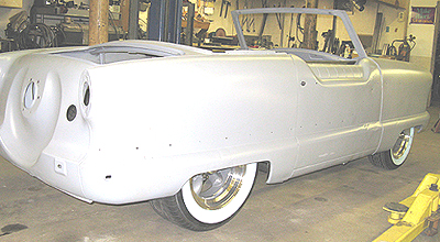
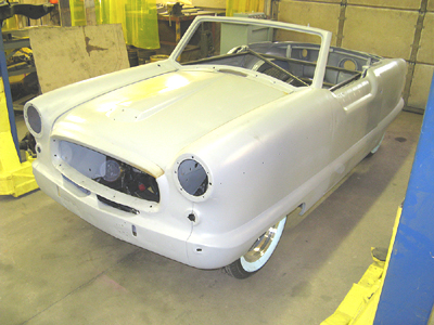
BELOW: Even though “low cut” front fender openings and tire clearance are a problem with these cars…there is still adequate turning angle.
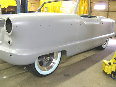
Tires are a good match for this car.
Whitewall tires up in the fenders…. LOOKS AWESOME!!
Considering that you can just about touch all four corners of the car with your hand without getting out of the seat…(not really!)… the build came out very nice. *** As you can see….at AUTO WELD….we always concentrate on quality first. *** Maybe you can glean some ideas from what we had to accomplish on this tight little car.
VERY COOL!!