Dimension & Worksheets
FOR SHOPS,
FABRICATORS, AND THE
HOME BUILDER
***
The following “drawings” and
“spec sheets” are also located
at other locations on our
web site!!
FRAME RAIL DESIGNS
***
Over the years we have made
many different frame rail shapes
and designs for ourselves and
for customers.
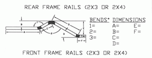
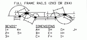
Below are three “frame rail
spec sheets” as examples that
you can use to help design
the frame rail shape that
is needed.
***
Other methods include sending
us a Cad drawing, detailed
sketch, or a cardboard template
of the shape that is needed.
Note: Cad drawings are sometimes
not reliable for fitting bends in
a certain shape. We always have
to correct the specs for a workable
pattern. Cardboard templates are
practical, simple and reliable.
***
Things to keep in mind when
planning a frame rail design….
*We use a 5 3/4″ inside radius
on all of our frame rail bends.
*You will need at least 6″
in between the bends.
*If we are working with sharp
angles that are too close
together…the bends may have
to be relaxed in the design in
order to complete bends.

***
*FRAME RAIL PATTERN DESIGN*
Below are three “dimension
sheets” to help you design a
workable pattern for your
project. These “spec sheets”
will provide additional information
that the above drawings
do not provide and should be
used in conjunction with them.
***
When purchasing a “Featherweight”
full chassis or a “Dream Chassis”
…we may need these dimensions.
***
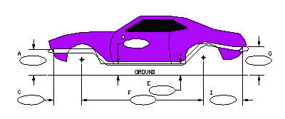
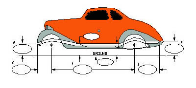
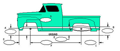
Choose the drawing that is the
most applicable to your project.
*Late model car
*Early model car
*Pickup truck
***
*REAR WELDED FRAME CLIP DIMENSIONS*
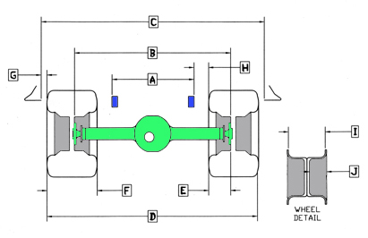
We use a build sheet that is
much like the form below. This
drawing will help you when plotting
out your frame and rear width.
***
To start:
First: measure inside fender lip
to inside fender lip…straight
up from the axle centerline.
This is usually the widest point
of the fender opening.
SECOND: Pick out your wheels and tires.
*You will need the tire “section width”
which is the total width
(bulge to bulge)inflated.
*You will also need the mfg’s “width”
and “backspace” of the wheels.
You will need these dimensions
to find the “total backspace”. A
measurement that is needed for
finding the “rear’s total width”.
***
Other things needed:
*Rocker panel “height” (measured in
front of the rear tire)
*Outside tire “diameter” or
tire height.
***DIMENSIONS***
(for above drawing)
***
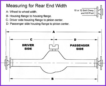
A….FRAME RAIL WIDTH
B….TOTAL REAR WIDTH (back of
wheel to back of wheel)
**NOTE: Deduct “rotor” or “drum”
thickness to find the “axle to axle”
dimension!
C….INSIDE FENDER LIP TO INSIDE LIP
(measured over axle centerline)
D….TOTAL TRACK WIDTH (outside tire width)
E….TOTAL BACKSPACE (backspace of wheel
plus the bulge of the tire)
F….WIDTH OF WHEEL AND TIRE (inflated)
G….CLEARANCE BETWEEN FENDER LIP AND
SIDEWALL OF TIRE
H….CLEARANCE BETWEEN FRAME RAIL AND
TIRE SIDEWALL
I….WHEEL WIDTH (measured in between
the “inside” lips of the wheels)
J….BACKSPACE OF WHEEL (measured from
the back edge of the rim to the
back of the wheel where it contacts
the axle)
***
**ADDED NOTE: When calculating
“total rear width”, add 1/2″
to each side of the wheel’s width.
***
(Example: A 15″ wide wheel is
actually 16″ measured at the
“outside” lips of the wheel.
Use this as a “rule of thumb”.
***
Remember!!…the wheel’s
“backspace” is also measured
from this outside point.
***
!! IF YOU NEED HELP WITH THE
DIMENSIONS, WE WILL BE GLAD TO
ASSIST YOU !!
****
***
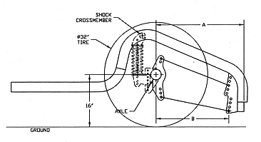
Shown: Profile and positioning
of front crossmember and the
axle relationship to the
lower front bracket hole.
***
**Competition 4 Link
A…approx. 26 1/4″
B…21 1/2″
Our “Competition 4-link’s
lower front bracket will be
6″ off the ground with a 32″
diameter tire.
***
**Ultimate II & Low Profile 4-Link
A…approx. 23 1/4″
B…18 3/4″
Our pro street 4-link’s
lower front bracket will be
8 1/2″ of the ground with
a 32” diameter tire.
****
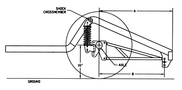
**LADDER BAR WELDED CLIPS**
***
Shown: Profile and positioning
of front crossmember and the
axle relationship to the lower
front bracket hole.
***
**Competition w/32″ Ladder Bar
A….33 7/8″
B….32″
**Competition w/36″ Ladder Bar
A….37 7/8″
B….36″
** Pro Street Ladder Bar
A….34 7/8″
B….33″
****
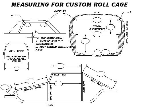
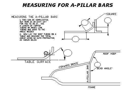
*ROLL CAGE SPEC SHEETS*
***
At AUTO WELD we make many different
types of roll bars and cages for cars
and trucks.
***
If you don’t see a particular roll cage
offered…..don’t despair!
Below are dimensioning sheets for you
to download, fill out, and fax back to
us. Most of the dimensions are simple
interior measurements. Upon receiving
them…..we can make the roll bar
or cage for you in the standard
ERW tubing. DOM and Chromoly are
additional. See the roll cage
“options” page.
Typically an additional “custom
charge” of $40-$50 is added to
the current roll bar or
roll cage prices.
